

Fuel cell testing system
As global demand for clean and renewable energy continues to rise, fuel cells have emerged as a highly efficient energy solution. To support the development and production of fuel cell engines, we are proud to introduce an advanced fuel cell testing system. This fuel cell testing system is designed to provide a stable and reliable testing platform, ensuring that they meet industry standards in functionality, performance, stability, and safety.
The fuel cell testing system consists of several key components, including a dedicated feedback electronic load, hydrogen supply module, air supply module, cooling module, and sampling control and protection module. The system utilizes proprietary testing software developed in-house, enabling efficient and accurate execution of various testing tasks, making it suitable for both research and development testing and post-production testing of fuel cell engines.
Our fuel cell testing system not only boasts comprehensive testing capabilities and robust safety mechanisms but also features a user-friendly interface and flexible data management capabilities. Whether for research and development testing or post-production verification, this system provides reliable support for fuel cell manufacturing, helping enterprises achieve breakthroughs in the clean energy sector.
Fuel cell testing system testing capabilities
In line with national standards, the fuel cell testing system can perform a variety of testing functions, including but not limited to:
- Hydrogen emission testing: Evaluating hydrogen emissions from the fuel cell engine under steady-state and cyclic conditions and recording relevant data.
- Gas tightness testing: Ensuring the gas tightness of the fuel cell to prevent leaks.
- Dynamic response characteristic testing: Measuring the dynamic response under various loads.
- Steady-state characteristic testing: Recording operational data at different power points to analyze system efficiency and hydrogen consumption rates.
- Aging testing: Simulating long-term use of the fuel cell to assess reliability.
- Insulation testing: Ensuring that the fuel cell’s insulation performance meets standards.

| FCTS-100 | FCTS-500 | FCTS-2K | FCTS-6K | FCTS-30K | FCTS-200K | |
| Power range | – 100 (W) | 100 – 500 (W) | 0.5 – 2 (kW) | 2 – 6 (kW) | 6 – 30 (kW) | 30 – 200 (kW) |
| Gas mass flow | Mass flow controller | |||||
| Standard anode flow (SLPM) | 0.5 – 2 | 2 – 10 | 5 – 50 | 15 – 150 | 60 – 600 | 500 – 5,000 |
| Standard cathode flow (SLPM) | 1 – 5 | 5 – 25 | 15 – 150 | 30 – 300 | 120 – 1,200 | 1,500 – 15,000 |
| Gas mixing | Option | |||||
| Humidification | Bubbler | |||||
| Temperature control | Max to 110˚C | |||||
| Bypass | Option (automatic) | |||||
| Coolant temperature control | Max to 90˚C | |||||
| Back pressure control (inlet/ outlet of stack) | 0.05 – 3 BarG | |||||
| E-load | 480W | Max 2kW | Max 12kW | Regenerative | ||
| CVM | Configuration on demand | |||||
| Dimensions (W×D×H mm) | 1600 x 700 x 1800 | 1600 x 1400 x 1800 | 3500 x 1600 x 2300 | |||
** The overall design of the fuel cell testing equipment can be customised on demand and non-standard manufacturing. According to the customer’s actual site conditions or testing needs, we provide customised fuel cell testing products to best match the customer’s needs.

FCTS-100

FCTS-2K / FCTS-6K

FCTS-200K
Technical advantages of gas state process control in fuel cell testing system
Our fuel cell testing system showcases outstanding technological advantages in gas state process control, ensuring accuracy and stability during testing. Here are the key technical features of the system:
Flow control
Flow control of the gas entering the fuel cell is critical. Our fuel cell testing system can achieve high precision in controlling gas flow under stable conditions of temperature, dew point, and back pressure. Even when gas flow changes, the dew point and back pressure remain stable, ensuring the efficient operation of the fuel cell.
In the diagram below, gas flow is shown in red, gas temperature in yellow and dew point temperature in green.
During changes in gas flow, the fuel cell testing system minimizes fluctuations in temperature, dew point, and back pressure through precise adjustment and a proactive feedback design. For low flow rates (below 1000 L), temperature fluctuations are less than 3°C; for high flow rates (above 1000 L), fluctuations are kept within 1°C, with pressure changes limited to less than 2 kPa.

Dew point and gas temperature control
The fuel cell testing system can precisely control both the dew point and gas temperature while maintaining a constant gas flow. With optional higher response control functions, the device achieves split flow control, ensuring stability in gas state during various operating conditions.
In the figure below, red is the gas flow, yellow is the gas temperature and green is the dew point temperature. The accuracy of gas flow control is ±0.8%RD+0.2%FS, and the accuracy of back pressure control is ±2kPa.
Changes in gas temperature can lead to variations in gas volume, which in turn affect flow rates. Our fuel cell testing equipment maintains stable flow even with temperature variations of up to 25°C. The control accuracy is ±0.8% RD + 0.2% FS, ensuring the reliability of the fuel cell system.

Back pressure control
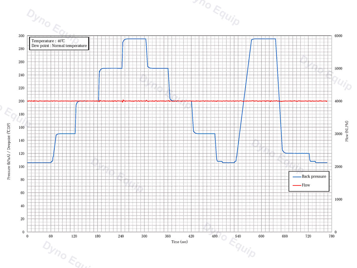
Our fuel cell testing system provides high responsiveness and precision in back pressure control, effectively managing changes in the fuel cell’s outlet pressure. When gas flow varies, the system can adjust accurately to avoid fluctuations in gas supply flow caused by changes in back pressure, ensuring a stable gas supply.
The figure below shows the gas flow rate in red and the back pressure in blue. The accuracy of gas flow control is ±0.8% RD + 0.2% FS, and the accuracy of back pressure control is ±2kPa (except when the atmosphere is open).
Fuel cell testing system testing functions
1. Hydrogen emission testing (GB/T 34593-2017)
- Purpose: To measure hydrogen emissions during steady-state and dynamic operating conditions.
- Process: The upper computer software records hydrogen flow rates, fuel cell stack voltage, and current, while calculating hydrogen emissions and air utilization rates.
2. Gas tightness testing (GB/T 24554-2009—7.9)
- Functionality: Conducts pressure retention tests.
- Steps:
- Close the hydrogen discharge valve, introduce hydrogen or inert gas (like nitrogen) into the fuel cell’s hydrogen line, and stabilize the pressure at 50 kPa (or user-specified pressure). After 20 minutes, record any pressure drop.
- Close the anode and cathode discharge valves, introduce hydrogen, air, or inert gas into both systems, stabilize pressure, and perform a similar retention test.
3. Dynamic response characteristics testing (GB/T 24554-2009—7.6)
- Objective: To assess the dynamic response under varying load conditions.
- Method: Load incrementally from a starting power point to a cutoff point, typically measuring the response time across 10% to 90% of the rated power.
4. Steady-state characteristics testing (GB/T 24554-2009—7.7)
- Goal: To evaluate the performance under stable operating conditions.
- Procedure: Select 10 power points (customizable), record operational data, and calculate:
- Hydrogen consumption rates under idle, 30% load, and rated conditions (g/kW*h).
- System efficiency at 30% load and rated conditions (%).
5. Aging testing (GB/T 19055-2003)
- Purpose: To simulate long-term operation and assess the reliability.
- Process: Based on the actual running time, this test mirrors automobile engine reliability testing methods.
6. Insulation testing (GB/T 24554-2009—7.10)
- Method: Measure the insulation resistance between the positive and negative terminals of the fuel cell stack against ground.
- Requirement: Insulation resistance must not be less than 100Ω/V.
7. Startup characteristics testing (GB/T 24554-2009-7.3)
- Data collected: Measure cold and hot startup times and the power supply.
8. Rated power testing (GB/T 24554-2009-7.4)
- Measurements: Record voltage, current, hydrogen consumption, and auxiliary system parameters during rated power operation.
9. Peak power testing (GB/T 24554-2009-7.5)
- Data Gathered: Monitor peak power operation time, system voltage, current, hydrogen consumption, and auxiliary system parameters.
10. Additional testing functions
- The fuel cell testing system can be customized to accommodate specific testing requirements based on user needs.
11. Real-time monitoring and anomaly alarms
- The fuel cell testing system continuously monitors pressure, temperature, voltage, current, hydrogen leakage, and safety conditions throughout the testing process. It executes protective measures according to different alarm levels and provides immediate alerts on the upper computer interface.

The fuel cell testing system advantages
- Design and functionality
Aesthetics and modularity: Our testing system features an aesthetically pleasing design with complete functional interfaces. The modular structure facilitates transportation and on-site installation, allowing for quick adaptation to various working environments.
- Safety protection
Comprehensive safety measures: The system is equipped with extensive safety features, including hydrogen leak detection, pressure, and temperature limit alarms. In the event of an alarm, the system can automatically shut down the electronic load and initiate nitrogen purging, ensuring a safe testing environment.
- Flexible testing capabilities
Multiple operating modes: The system supports a wide range of input voltages and currents for the electronic load, including CV (Constant Voltage), CC (Constant Current), and CP (Constant Power) modes. Operators can easily design test plans through a user-friendly interface to meet various load testing needs.

- Robust monitoring and data management
Real-time monitoring and data storage: The system includes powerful monitoring software that allows for real-time observation of test data, which can be saved for later analysis. Test data can be represented graphically, facilitating intuitive comparison and analysis.

- Flexibility in manual and automated testing
Human-machine interaction: During automated testing, operators can intervene at any time to skip, pause, or terminate tests. The system also supports manual adjustment, enabling users to tweak valve control, water cooling temperature, and other parameters as needed.
- Reliable data communication capabilities
CAN communication support: The system is capable of real-time data collection and transmission via a CAN network, ensuring data integrity and accuracy. Users can also customize communication protocols to meet specific testing requirements.
Fuel cell testing system composition
- Cooling system
The water cooling system employs multiple loops for efficient thermal management. The primary loop is designed to maintain stable temperatures across various operating conditions, while the external loop provides stable external conditions. The intermediate loop adjusts based on the thermal needs of the fuel cell.
- Hydrogen/ nitrogen supply system
This system consists of both nitrogen purging and hydrogen supply components. Nitrogen purging is available before and after fuel cell engine testing to ensure cleanliness. Key components include control ball valves, safety pressure relief valves, manual pressure reducing valves, and electromagnetic valves, all equipped with pressure sensors, flow sensors, and hydrogen leak detectors for safety.
- Thermal management system
This system includes main and auxiliary cooling units, utilizing a three-tier cooling circuit for efficient heat exchange. Components include control valves, plate heat exchangers, water tanks, and electric heating modules to maintain temperature control for fuel cell engines.
- Power distribution module
The system includes both low-voltage and high-voltage power distribution modules, providing stable power to the engine system and its auxiliary devices to ensure normal operation.
- Exhaust emission system
This component provides a pathway for the discharge of exhaust gases following the reaction in the fuel cell engine, with standard configurations enabling safe hydrogen-air mixed emissions.
- Feedback electronic load
The system features a DC feedback electronic load, allowing for the complete recovery of generated energy, maximizing resource efficiency.
- Control system
Responsible for data collection and operational control of the system, ensuring stable performance throughout testing.
- Human-machine interface
The user-friendly upper computer interface allows operators to easily manage tests, including task editing, real-time fault monitoring, and data transmission, facilitating long-term unattended operation.
- Water purging system
After testing, the fuel cell engine can initiate water purging in the cooling circuit to ensure no residual moisture remains in the equipment.
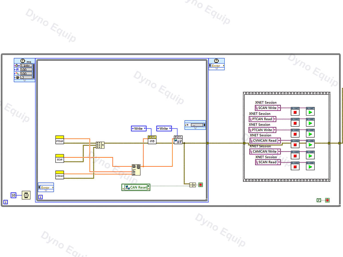
- CAN Communication
The system supports CAN communication protocols with the engine, allowing for custom protocol development based on client requirements.
- Hydrogen discharge circuit
In cases of excessive pressure in the hydrogen circuit, the system can promptly depressurize and issue alarms for safety.
- Sensor sampling system
Comprising hydrogen leak detectors, temperature sensors, flow sensors, etc., this system ensures safety during testing and initiates emergency shutdown protocols in case of leaks.
- Safety protection system
A comprehensive combination of hardware and software protection measures ensures safe operation under all circumstances.
Sitemap